Background
During the last 10 years, advanced applications have been using X-rays in the operation room together with other components, like navigation systems or CT over X-ray visualization systems, to support the surgeon in some of his or her tasks.
C-arm images, like many camera images, suffer from distortion (typically barrel and/or pincushion distortion). Calibration is needed to align images and match accurately the physical object being scanned. The outcome is highly accurate image, which can be used for both visual navigation as well as registration with other involved systems (CT and tracking systems).
Camera calibration is the first phase of computer-aided orthopedic surgeries. It enables high accuracy navigation into the orthopedic environment under operation. The C-Arm calibration process ensures undistorted scans, which easily registered with both the navigation system and the patient’s pre-operation CT scan.
Procedure
C-Arm, in-op (during operation) camera calibration of X-ray images can be performed in one of the following ways:
- Offline: when the calibration process is performed before the surgery and its calculated calibration data is used during the surgery to correct scan distortion.
- Online: when additional reference data is extracted from the scans during the surgery and used to calculate the distortion. This data is the outcome of a calibration jig, attached in the front of the camera.
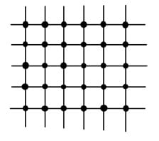
Offline calibration is engaged pre-op (before the surgery), when no patient is in the surgery room. Calibration is performed using a jig which is positioned on the operation table. The jig is formed as a standard grid of balls. The calibration process starts by capturing a few scans of the jig while the camera is positioned in predefined angles. The angles used are the same angles which are planned to be used during the surgery. This way, a set of calibration correction data is prepared- for each scan which will be taken in-op. The scan has the format of a 2D image and the balls location is extracted using a dedicated detection algorithm. The location of each ball in the scan relative to its location in the reference jig is used to form the distortion correction data. In addition, the inner distance between the balls is used to calculate the pixel size. The advantage of offline calibration is its high accuracy, owing to the jig location (within the patient) and simpler in-operation procedure (no need to perform the calibration while the patient is on the surgery bad).
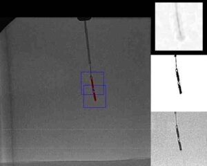
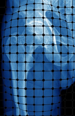
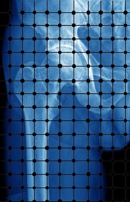
Online calibration is performed during the surgery. This means that the scans of the patient are matching his or her position and orientation during surgery procedure. The jig, in this case, is attached to the camera, just in the front of it. For each angle, required for the procedure, two scan are performed: one with the jig attached in the front of the camera and the other without the jig. The first scan shows the jig balls superimposed on the patient image. A dedicated algorithm extracts the balls, calculates the distortion correction and extrapolates the pixel size. This method is potentially less accurate than the offline method. However, it ensures the correction is fine tuned to the actual image, so that calibration deterioration is eliminated.
Typical camera distortion types are pincushion and barrel distortion. Please refer to the following figures:
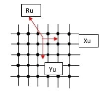
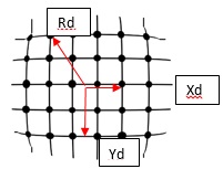
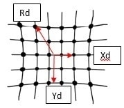
Barrel and pincushion distortion can be modeled as follows, based on Zhang Z. (1999) “Flexible camera calibration by viewing a plane from unknown orientation” and Andrew W. Fitzgibbon (2001) “Simultaneous linear estimation of multiple view geometry and lens distortion”.
Ru = Rd (1 + K*Rd2)
Zhang, 1999 showed that the polynomial radial distortion model with two coefficients can be modeled as:
rd = r (1 + k1r2 + k2r4)
rd = ru (1 − α|ru|2) ↔ ru = rd1 – αrd2
where ru and rd are the distances from the center of distortion in the undistorted and distorted images. α is a constant specific to the lens type used.
In addition – see van der Maas, R. J. R. (2016) “Advanced geometric calibration and control for medical X-ray systems” – the calibration parameters can be separated in a known reference part and an unknown part due to system imperfections and disturbances (since high order disturbances are observed).
This is the first in a series of five articles about Orthopedic Navigation. Read the next article about CT Segmentation in Orthopedic Surgeries.